+86 13630122007


Choosing the right Servo Motor begins with the machine, not the catalogue. A motor that performs beautifully on a test bench may struggle on a packaging line. Load weight, acceleration, duty cycle, speed, and available space all matter. So does the driven mechanism. A belt drive, ball screw, or direct coupling changes the motor’s real workload.
Motion-control specialist Peter Nachtwey offers a useful reminder: “A servo system is only as good as the mechanics it drives.” The statement is practical, even if engineers sometimes overlook it. Backlash, vibration, poor alignment, and flexible couplings can weaken precise control. More torque will not always fix those problems.
This guide examines the decisions behind a dependable Servo Motor selection. It considers continuous torque, peak torque, inertia matching, encoder resolution, voltage, braking, and amplifier compatibility. Thermal conditions deserve attention too. A motor inside a sealed cabinet may need more capacity than its calculations suggest. Dust, washdown, and repeated stops can also change the specification.
There is no perfect choice. Only a suitable one.
In real projects, early estimates can be wrong. That is normal. A designer may calculate the load correctly but underestimate friction or acceleration time. Testing under actual operating conditions remains essential. Measure current, temperature, settling time, and vibration. Then revise the selection before production begins. That small step can prevent oversized hardware, unstable motion, and expensive downtime.
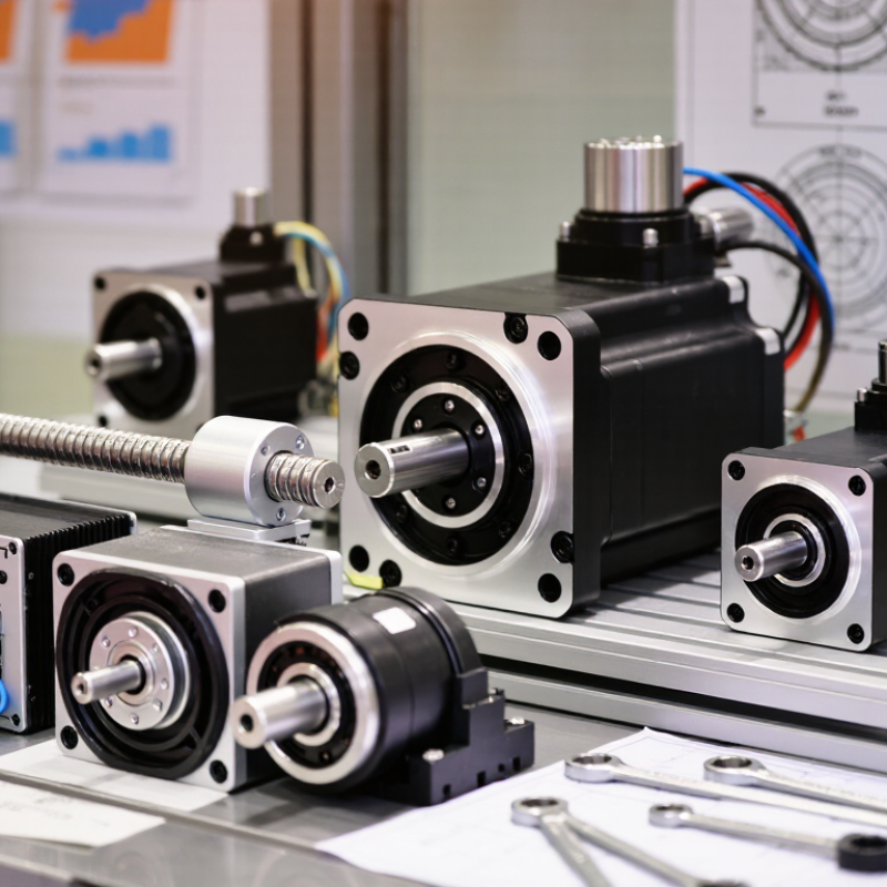
Choosing a servo motor starts with motion, not motor size. Describe every move: distance, speed, acceleration, settling time, and cycle frequency. A conveyor indexing 300 millimeters differs greatly from a rotary table moving five degrees.
Measure the real load. Include tooling, product weight, friction, gearbox inertia, and vertical forces. Estimate torque with load torque plus inertia multiplied by acceleration. Then check continuous and peak torque separately. A motor may survive a short peak but overheat during repeated cycles.
Positioning needs equal care. Define allowable error, repeatability, backlash, and vibration at the machine output, not only at the shaft. For a 0.1-millimeter target, belt stretch and frame flex may matter more than encoder resolution.
According to ISO 9283, robot performance testing considers position accuracy, repeatability, and path-related behavior. Those ideas also apply to linear stages and pick-and-place equipment.
In commissioning work, a spreadsheet can look exact, yet acceleration is often guessed too low. Leave thermal and torque margin, but do not hide poor mechanics behind an oversized motor.
Measure one full production cycle, including pauses, reversals, and emergency stops. The forgotten pause matters.
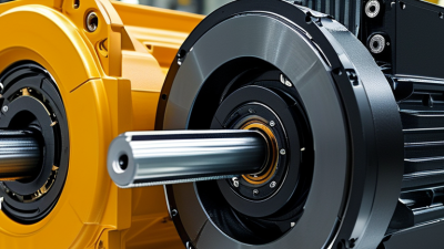
A servo motor should fit the machine’s real load, not only its catalog rating. Start by recording moving mass, friction, pulley diameter, duty cycle, and required acceleration. A vertical axis also needs gravity and holding torque included. Small details matter. Measure them.
Calculate continuous torque for normal motion, then check peak torque during acceleration and braking. Leave a practical margin, often 20 to 30 percent, but do not oversize blindly. An oversized motor can reduce control sensitivity, increase cost, and waste energy. For a screw-driven slide, estimate torque from thrust, screw lead, efficiency, and acceleration. For a belt axis, include pulley radius and tension. Use actual test data when available. My field experience suggests that estimated friction is often too optimistic.
Speed selection needs equal care. Confirm the motor can reach the target speed without losing torque. Compare the load’s reflected inertia with the motor inertia, especially during rapid reversals. A high ratio may improve matching, but it can add backlash and mechanical stress. Check encoder resolution, amplifier compatibility, thermal limits, and stopping distance together. Run a short trial with the heaviest product and the fastest cycle. If vibration appears, do not simply increase gain; inspect resonance, coupling alignment, and acceleration settings. Real machines rarely behave like spreadsheets.
How to Choose the Right Servo Motor for Your Machine?
Select the Appropriate Feedback, Drive, and Control System
Servo selection starts with the feedback device, not the motor nameplate. An encoder provides precise position data for indexing, pick-and-place, and electronic gearing. A resolver can tolerate heat, dust, and vibration better in harsh areas. Check resolution, response time, cable length, and mechanical backlash before choosing. A high-resolution sensor cannot correct a loose coupling.
The drive must match the motor’s voltage, current, braking, and overload requirements. It also needs suitable tuning software and safety functions. The International Federation of Robotics reported 541,302 industrial robots were installed worldwide in 2023. This growth increases demand for stable motion control, not just higher speed. A drive with weak regenerative handling may overheat during rapid deceleration. That detail is often missed. Control compatibility matters too. Confirm communication cycles, synchronization, interpolation, and controller update rates. A fast motor can still perform poorly with slow commands.
Tips: Measure the real load first. Record torque peaks, cycle time, inertia, and stopping distance. Then test the motor, feedback, drive, and controller together. According to the International Federation of Robotics’ World Robotics 2024 report, 4.28 million industrial robots were operating globally in 2023. That scale shows why repeatability and diagnostics deserve equal attention. Do not trust simulation alone. Real cables flex, bearings wear, and temperature changes tuning. The “perfect” configuration may not exist, but a measured compromise usually works better.
| Machine Requirement | Typical Motion Profile | Recommended Feedback | Suitable Drive Function | Preferred Control Method | Key Motor Selection Criteria | Design Considerations |
|---|---|---|---|---|---|---|
| High-Speed Indexing | Rapid acceleration, deceleration, and repeated positioning | Incremental encoder | Position loop with electronic gearing and acceleration limiting | Pulse train, EtherCAT, or other deterministic fieldbus | Low rotor inertia, high peak torque, fast encoder response, and sufficient overspeed capability | Verify settling time, mechanical backlash, coupling stiffness, and heat generation during repetitive cycles |
| Precision Assembly | Low-speed motion with precise final positioning | High-resolution absolute encoder | Closed-loop position and velocity control with notch or vibration suppression | Real-time motion network or high-speed pulse command | High encoder resolution, low cogging torque, repeatability, and stable low-speed operation | Use rigid mounting, minimize compliance, and account for thermal expansion in the machine structure |
| Continuous Web or Film Handling | Constant speed, tension control, and coordinated shaft motion | Incremental encoder or resolver | Velocity control with torque or tension control capability | Analog reference, fieldbus, or synchronized line-shaft control | Continuous-duty thermal rating, smooth torque, speed stability, and adequate overload capacity | Include dancer-roll or load-cell feedback where tension must be regulated; avoid sudden torque changes |
| Vertical Lift or Z-Axis | Vertical positioning with static load and frequent stops | Absolute encoder with holding-brake feedback | Position control with brake sequencing and safe torque-off | Safety-rated fieldbus or coordinated motion controller | Continuous and peak torque, brake holding capacity, load inertia, and regenerative braking capability | Calculate torque for gravity, acceleration, friction, and emergency stopping; never use the motor brake as the primary dynamic brake unless approved for that duty |
| High-Inertia Rotary Load | Moderate speed with substantial acceleration and deceleration demand | Absolute or incremental encoder | Auto-tuning drive with inertia identification and regenerative management | Fieldbus, pulse train, or analog command depending on coordination needs | Peak torque, reflected inertia ratio, braking resistor capacity, and mechanical resonance control | Use a suitable gearbox or higher-torque motor when necessary; confirm that reflected load inertia remains within the drive tuning range |
| Multi-Axis Synchronized Motion | Coordinated interpolation, electronic camming, or gearing | Absolute encoder with network position feedback | Multi-axis coordinated control with deterministic synchronization | Real-time industrial Ethernet or synchronized motion bus | Network cycle time, synchronization accuracy, encoder update rate, and torque reserve | Use a common motion profile and verify clock synchronization, axis scaling, cable length, and network loading |
| Harsh or Contaminated Environment | Variable-speed motion exposed to dust, moisture, vibration, or washdown | Resolver or sealed absolute encoder | Closed-loop velocity or position control with environmental fault monitoring | Shielded fieldbus, industrial I/O, or protected pulse interface | Ingress protection, temperature range, vibration resistance, connector sealing, and cable durability | Confirm the complete motor, connector, feedback, and cable assembly rating; the weakest component determines practical environmental protection |
| Cost-Sensitive Variable-Speed Axis | Moderate accuracy with limited dynamic performance requirements | Incremental encoder | Basic closed-loop velocity or position control | Pulse train, analog command, or standard industrial network | Required accuracy, operating speed range, continuous torque, and total installation cost | Do not select by motor price alone; include the drive, feedback device, cables, braking components, commissioning time, and maintenance requirements |
A servo motor must fit the machine before its performance matters. Measure the mounting flange, shaft diameter, keyway, and available space. Check the motor’s continuous and peak torque against the load. A heavy rotating load may also require careful inertia matching.
I once selected a motor with enough torque, but its shaft length caused a coupling problem. That mistake delayed testing. Review the mechanical drawing, not only the product description.
Environmental conditions can quietly shorten service life. Check ambient temperature, dust, moisture, vibration, and cleaning methods. Choose suitable protection levels for exposed installations. A motor near coolant needs stronger sealing than one inside a clean cabinet.
Power compatibility is equally important. Confirm voltage, current, phase requirements, feedback type, and drive compatibility. Compare continuous power with the machine’s duty cycle. Peak ratings alone can mislead.
Some calculations remain uncertain without real acceleration data, so test the load when possible.
Tips: Record the load mass, speed, acceleration, and stopping time. Leave reasonable thermal margin. Verify cable routing and connector clearance. Ask a qualified engineer to review unusual loads or harsh environments. Small details matter. Rethink assumptions before ordering.
Motor choice should begin with lifetime cost, not catalogue price. Purchase price is visible; electricity, stoppages, spares, and technician hours are not. The U.S. Department of Energy’s Improving Motor and Drive System Performance sourcebook estimates that motor systems consume 69% of industrial electricity. That makes efficiency a production issue, not merely an energy issue. Record load, duty cycle, ambient temperature, acceleration, and brake requirements before comparing quotations. A perfect rating on paper can fail in dust.
The U.S. Department of Energy’s Operations & Maintenance Best Practices Guide reports that predictive maintenance can reduce maintenance costs by 25–30% and downtime by 35–45%. Those figures are guidance, not a promise. A retrofit may need sensors, programming, alignment, and staff training. Price those items openly. Compare bearings, encoder protection, spare availability, service intervals, and expected repair time. Price maintenance too. A lower-cost motor with repeated thermal trips can erase its purchase savings within months.
Reliability also depends on matching the motor to the machine’s real operating profile. IEC 60034-30-1 efficiency classes help compare rated efficiency, but they do not predict every site failure. Use measured current and temperature data when possible. Ask how maintenance will be performed at 2 a.m., not only how the motor performs at acceptance. That question exposes labor, access, and inventory costs. I would leave a contingency allowance; operating conditions rarely stay ideal. That is an uncomfortable assumption.