Leave Your Message

How to Choose the Right Cutting Tool for Your Needs?

Choosing the right Cutting Tool is rarely a simple matter of selecting the hardest edge. The best choice depends on the workpiece material, machine capability, cutting speed, feed rate, and required surface finish. A tool that performs well on aluminum may fail quickly on hardened steel. Even small changes in coolant flow or workholding can affect results.

In practical machining, I begin by examining the material and the operation. Turning, milling, drilling, and threading each require different tool geometries. Carbide inserts may suit high-volume steel production, while high-speed steel can remain useful for slower work and frequent resharpening. Coatings also matter. Titanium aluminum nitride, for example, may improve heat resistance under suitable conditions, but it cannot fix poor setup or excessive vibration. Check the manufacturer’s data before adjusting speeds and feeds.

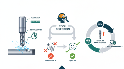
The first choice is not always perfect. I have seen a tool selected by price create more downtime than savings. That lesson is easy to overlook. Measure twice. Record tool life, chip shape, edge wear, and finished dimensions during testing. These details provide stronger evidence than assumptions or marketing claims. A reliable decision balances performance, safety, machine limits, and total operating cost. If uncertainty remains, start with a conservative trial and inspect the result closely. Good tool selection is a repeatable process, but it still requires judgment, experience, and occasional reconsideration.

How to Choose the Right Cutting Tool for Your Needs?

Define the Cutting Task and Material Requirements

Choosing a cutting tool begins with the task, not the catalog. Define the operation clearly: roughing, slotting, drilling, finishing, or interrupted cutting. Record the workpiece grade, hardness, thickness, and surface condition. A stainless bar behaves differently from cast iron, even at the same diameter. Consider machine power, spindle speed, coolant access, and workholding stability. These details determine edge geometry, coating needs, and cutting parameters.

ISO 3685 recommends evaluating tool life through controlled cutting tests, rather than relying only on supplier tables. That matters because vibration, overhang, and heat can change results quickly. The U.S. Manufacturing Institute and Deloitte estimated that 2.4 million manufacturing positions could remain unfilled between 2018 and 2028. Skilled judgment is still essential. A report cannot feel chatter through the machine frame. I have learned this the hard way.

Material data should guide the first trial. High-strength alloys often need tougher edges and lower cutting speeds. Aluminum may require sharper geometry and effective chip evacuation. According to a 2024 global cutting-tools market analysis, demand continues to grow with advanced manufacturing and automation. That growth does not make selection simpler. Start with the material’s tensile strength, hardness, and abrasiveness. Then match the tool to the actual cut length and tolerance. Leave room for adjustment. Real production rarely behaves perfectly. A clean spreadsheet can still miss a loose fixture or a worn spindle. Record tool life, chip shape, surface finish, and temperature after each trial. These observations make the next choice more reliable.
Compare Cutting Tool Types and Their Best Applications

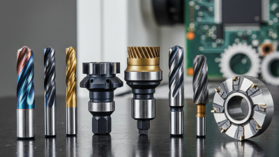
Choosing a cutting tool starts with the workpiece, not the catalog page. Compare the material, feature, tolerance, and machine rigidity. A carbide twist drill suits general holemaking in steel and aluminum. A reamer gives better size control after drilling. For pockets and slots, an end mill removes material efficiently, while an indexable cutter handles larger faces and repeated production passes.

The application changes the best choice. Use coated carbide for higher cutting speeds and longer edge life in many steels. Choose ceramic only when the machine is rigid and heat control is reliable. Abrasive wheels remain practical for hardened parts and fine finishing. They cut differently, so forcing one tool into every task creates heat, vibration, and premature wear. It happens more often than people admit.

A 2024 Grand View Research report estimated the global cutting tools market at more than 24 billion U.S. dollars, with continued growth driven by automation and precision manufacturing. That growth does not make selection easier. The U.S. Department of Energy’s machining guidance also links tool condition, cutting parameters, and energy use. In practice, I record chip color, edge wear, sound, and cycle time during a short trial. The first choice is rarely perfect. A sharper tool may improve finish but fail under interrupted cuts. A stronger edge may survive, yet leave a rougher surface. Check the result against the drawing, not intuition.

How to Choose the Right Cutting Tool for Your Needs?

Typical cutting-speed ranges by tool type and their best applications

Indicative turning-speed ranges in meters per minute. Actual values vary with workpiece hardness, tool geometry, feed rate, depth of cut, coolant, and machine rigidity.

High-Speed Steel
Best for drills, taps, small batches, and interrupted cuts in steel and softer metals.
Cemented Carbide
A versatile choice for general-purpose turning, milling, and drilling across common metals.
Ceramic
Suitable for high-speed finishing of hardened steels and cast irons under stable conditions.
CBN
Best for hardened ferrous alloys, hard turning, and long tool life in finishing operations.
PCD
Ideal for high-speed machining of aluminum, copper alloys, composites, and other non-ferrous materials.

Evaluate Tool Material, Geometry, and Edge Design

How to Choose the Right Cutting Tool for Your Needs?

Tool selection begins with material, not appearance. Carbide suits hard alloys and steady production, while high-speed steel tolerates shock and lower cutting speeds. A 2024 global cutting-tools market report estimates carbide tools hold more than half of worldwide revenue. That share reflects durability, but not every workshop needs maximum hardness. Brittle carbide can fail quickly on interrupted cuts.

Geometry controls how the tool behaves at the workpiece. A larger rake angle lowers cutting force and helps soft aluminum form cleaner chips. A smaller rake angle strengthens the edge during hard-steel cutting. Helix angle also matters. Higher helix designs often evacuate chips smoothly, while lower helix designs can reduce edge damage in brittle materials. ISO 3685 recommends controlled tool-life testing under defined cutting conditions. In practice, many operators skip this step. That is a costly habit.

Edge design deserves close attention. A sharp edge reduces burrs and cutting heat, but it may chip under vibration. A honed edge offers better strength, although it can increase cutting pressure. Coatings may extend life, yet their value depends on speed, coolant, and workpiece chemistry. The U.S. Department of Energy’s manufacturing assessments repeatedly identify process optimization as a major efficiency opportunity. My own shop records show the same pattern: small geometry changes sometimes outperform expensive material upgrades. Not always. Measure flank wear, surface finish, and power draw before making a final choice.

How to Choose the Right Cutting Tool for Your Needs? – Evaluate Tool Material, Geometry, and Edge Design

Tool Material Typical Geometry Edge Design Suitable Work and Conditions Main Trade-Off
High-speed steel (HSS) Often ground with a relatively positive rake and generous clearance; geometry can be tailored for drills, taps, and form tools. A sharp, honed edge is common; avoid an excessively fragile edge when interrupted cuts or vibration are likely. General-purpose machining, low-to-moderate production rates, complex tool shapes, and applications where toughness or easy resharpening matters. Tough and relatively easy to sharpen, but it generally cannot sustain the cutting speeds of carbide or many advanced cutting materials.
Cemented carbide Available in a wide range of rake angles, chipbreakers, and insert shapes; positive geometries suit lower cutting forces, while stronger geometries suit heavier cuts. A sharp edge suits continuous, light cutting; a small hone or chamfer can strengthen the edge for heavier cuts or interrupted machining. A broad range of turning, milling, and drilling operations on steels, cast irons, and nonferrous metals, depending on grade and coating. Offers higher wear resistance and cutting speed than HSS in many applications, but is less tolerant of impact and vibration.
Ceramic Typically uses a robust insert shape and a geometry selected for stable, often high-speed cutting. A reinforced edge is often preferred to reduce chipping; a very sharp, thin edge may be unsuitable for unstable cuts. High-speed finishing or semi-finishing of suitable cast irons and heat-resistant alloys; performance depends on ceramic type and setup stability. Retains hardness at high temperatures, but is comparatively brittle and sensitive to shock, vibration, and abrupt thermal changes.
Cubic boron nitride (CBN) Commonly supplied as a cutting-tip segment or insert; geometry and grade are chosen for the workpiece hardness and whether the cut is continuous or interrupted. A honed or chamfered edge can improve edge strength, particularly in hard turning or less stable cuts. Hard turning of hardened ferrous materials and machining of certain hard cast irons, when the machine and workholding are sufficiently rigid. Very high hot hardness and wear resistance for suitable ferrous applications, but cost and edge brittleness can limit its use.
Polycrystalline diamond (PCD) Often uses a sharp, polished geometry with positive rake to promote clean cutting and reduce built-up material on the edge. A sharp, low-radius edge is useful for fine finishes; edge strength should still be matched to abrasive content and cutting stability. Nonferrous metals such as aluminum, as well as some composites and other abrasive nonmetallic materials. Provides excellent wear resistance and finish in suitable materials, but is generally unsuitable for machining ferrous alloys at elevated cutting temperatures.

Selection note: Match the tool to the workpiece material, operation, machine rigidity, and desired finish. Positive rake generally lowers cutting forces but can weaken the edge; a honed or chamfered edge can improve strength but may increase cutting forces.

Match Tool Size, Compatibility, and Operating Conditions

How to Choose the Right Cutting Tool for Your Needs?

Match Tool Size, Compatibility, and Operating Conditions

Choosing a cutting tool is less about sharpness than fit. Start with the material, cut depth, and available machine power. A compact tool may struggle in dense stock. Measure the workpiece before ordering. For a 20-millimeter slot, a 10-millimeter cutter may need two passes. That detail affects heat, load, and surface quality.

Match the tool size to the machine’s chuck, collet, or arbor. Check diameter limits, clearance, and maximum rated speed. Compatibility includes the workholding system, not only the shank. During workshop trials, watch for vibration, deflection, and unusual dust. These signs often reveal a poor match before visible damage appears. Keep the speed conservative when the material or setup is unfamiliar. I once trusted a rigid-looking fixture. It was not.

Operating conditions can change the correct choice. Dry cutting, coolant-fed cutting, and intermittent cutting create different stresses. Consider temperature, chip control, visibility, noise, and access around the workpiece. Use technical data, then verify it with a controlled test cut. Record feed, speed, pass depth, and edge wear. If the finish worsens, inspect the setup instead of forcing the tool. Selection notes are never perfect; material batches vary, and assumptions can hide mistakes. Small checks matter.

Balance Performance, Durability, Safety, and Cost

Choosing the right cutting tool starts with the workpiece, not the tool cabinet. Identify the material, hardness, cut depth, tolerance, and machine rigidity. Aluminum may reward sharp edges, while hardened steel often needs stronger geometry and controlled speed. Check published operating ranges, then confirm them with a small trial cut. Watch the chip shape, cutting sound, and surface finish during that test. These details reveal problems faster than appearance alone.

Balance performance with durability instead of chasing the highest cutting speed. A fast tool can shorten cycle time, but excessive heat may destroy its edge quickly. Choose a tool that produces stable results across the planned batch. Cost should include inserts, setup time, rejected parts, coolant, and downtime. I once treated the purchase price as the main measure. That decision looked sensible, but frequent changes made production more expensive. Safety remains non-negotiable. Secure the workpiece, inspect the tool, and follow the machine’s limits. A guarded setup and proper eye protection reduce avoidable exposure to chips. Even experienced operators can miss early vibration.

Tips: Begin with a conservative speed and feed. Record tool life and surface results. Compare cost per finished part, not cost per tool. Stop when vibration, cracking, or unusual heat appears. Review the choice afterward; real results may challenge the original calculation.