+86 13630122007


Choosing the right Spindle Motor in 2026 requires more than comparing speed and price. Global buyers must match motor performance with machine design, materials, duty cycles, and local operating conditions. A compact workshop router may need a 2.2 kW air-cooled motor. A production machining center may require higher torque, liquid cooling, and precise feedback control.
Small details matter.
This guide examines the practical factors behind a dependable purchase. It covers power ratings, rated speed, torque curves, bearing quality, collet standards, cooling methods, noise levels, inverter compatibility, and maintenance access. It also considers supplier experience, technical documentation, warranty terms, spare parts, and shipping support. Buyers should request test data, installation drawings, and clear information about operating limits. A polished product page is not enough.
Real-world performance can differ from catalog claims. Dust, voltage fluctuations, poor alignment, and incorrect lubrication can shorten service life. Even a well-designed Spindle Motor may fail when installed without proper balancing or programming. That point is easy to overlook. We also recognize that no single motor suits every country, machine, or budget. Certification needs, electrical standards, and after-sales resources vary between markets.
The recommendations ahead are designed to support careful comparison, not rushed purchasing. They combine engineering principles with practical inspection questions. Some conclusions remain conditional. That is honest. A reliable decision comes from verifying specifications, evaluating the supplier, and considering the complete operating environment.
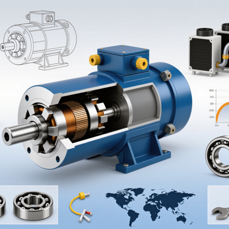
Selecting a spindle motor starts with the cutting task, not the catalog headline. Industry reports from the International Energy Agency estimate that electric motors consume roughly half of global electricity. Efficiency matters, even in compact machine tools. For light engraving, plastics, and small aluminum parts, 0.8–3 kW at 18,000–24,000 rpm can provide responsive cutting. These motors often deliver limited low-speed torque.
Power alone can mislead. Use T = 9550P/n to estimate torque in newton-metres. A 24 kW motor at 18,000 rpm produces about 12.7 Nm. At 60,000 rpm, the same motor produces only 3.8 Nm. High speed suits small tools and fine surface work. Lower speed with higher torque suits larger cutters and harder materials.
Real output also depends on the inverter, bearings, cooling, and tool balance.
Duty classification deserves equal attention. S1 supports continuous operation. S6 handles repeated load and no-load periods, but its allowable heating differs. ISO 230-4 testing principles can help evaluate spindle thermal and positioning behavior.
In practice, I would check rated torque curves instead of trusting peak power. A 24 kW label looks impressive. It may still disappoint during heavy interrupted cuts.
Cooling capacity is often underestimated. Mistakes happen here.
Record tool diameter, material, cycle time, and actual load before choosing the final speed range.
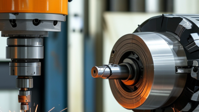
A spindle motor should be matched to the cutting load, not selected by headline speed. Read the torque curve at the real operating speed. Aluminum may need high rpm and modest torque, while steel demands stronger low-speed torque and better thermal control. Small details matter, including tool diameter, chip load, acceleration, and interrupted cuts.
IEC 60034-1 defines S1 as continuous duty at constant load until thermal equilibrium. Choose it for long, steady machining cycles. S6 describes periodic continuous operation, combining load and no-load periods without a complete stop. It suits repeated cutting cycles, but only when the manufacturer provides duty-cycle limits. A 40% load period is not automatically safe; torque, cooling, and ambient temperature still change the result. I have seen buyers trust the duty label and ignore peak torque. That mistake becomes expensive.
The IEA’s Energy Efficiency 2023 analysis estimates electric motor systems consume about half of global electricity, making efficiency and thermal design important purchasing factors. IEC 60034-30-2 also provides efficiency classifications for variable-speed motor systems. Ask for measured torque curves, S1 or S6 test conditions, and efficiency data at your actual speed range. A motor rated at 24,000 rpm may deliver far less torque below 6,000 rpm. Check that point carefully. Supplier data can look complete, yet omit continuous torque, bearing limits, or inverter assumptions. That omission deserves questions.
| Workpiece Material | Typical Machining Process | Recommended Spindle Speed Range | Typical Cutting Speed Reference | Recommended Continuous Power Range | Useful Torque Range at Cutting Speed | Preferred Torque-Curve Characteristic | Recommended Duty | Cooling and Protection Considerations | Selection Comments |
|---|---|---|---|---|---|---|---|---|---|
| Aluminum alloys | High-speed milling, drilling, engraving and light turning | 12,000–30,000 rpm | 200–600 m/min for carbide tools, depending on alloy and tool diameter | 3–15 kW | 1.0–12.0 N·m at 12,000 rpm | High constant-power range above base speed; adequate overload torque for acceleration and interrupted cuts | S1S6-40% | Air cooling is common for moderate power; liquid cooling is preferred for high continuous power or thermal stability. Use at least IP54 enclosure protection where coolant is present. | Prioritize high maximum speed, low rotor imbalance, short acceleration time and a low minimum speed if large-diameter tools are also used. |
| Mild steel and low-carbon steel | General milling, face milling, drilling and turning | 3,000–12,000 rpm | 80–250 m/min for carbide tools; lower values are common with high-speed steel tools | 5.5–30 kW | 8–95 N·m at 3,000 rpm | Strong constant-torque region from low speed to base speed, followed by controlled constant-power operation | S1S6-40% | Liquid cooling is generally suitable for continuous production. Confirm bearing temperature limits, coolant compatibility and encoder protection. | Torque at low and medium speed is usually more important than maximum rpm. Check the torque curve rather than relying only on rated power. |
| Stainless steel | Heavy milling, slotting, drilling, tapping and turning | 1,500–8,000 rpm | 40–150 m/min for carbide tools, depending on grade, tool geometry and cooling | 7.5–37 kW | 20–235 N·m at 1,500 rpm | High overload capability and stable torque below base speed; limited torque drop during thermal loading | S1S6-40% | Liquid cooling is normally preferred. Select bearings and seals for heat, chips and coolant exposure; provide adequate thermal monitoring. | Choose a motor with sufficient low-speed torque and overload margin to reduce chatter, work hardening and tool breakage. |
| Cast iron | Face milling, boring, drilling and interrupted cutting | 2,000–10,000 rpm | 80–250 m/min for carbide tools, depending on grade and hardness | 5.5–30 kW | 12–143 N·m at 2,000 rpm | High peak torque, good dynamic stiffness and controlled acceleration for interrupted engagement | S1S6-40% | Use sealed bearings and effective chip protection. Air cooling can be adequate at lower power, but liquid cooling improves thermal consistency. | Evaluate peak torque, torsional stiffness and bearing load capacity in addition to rated speed and power. |
| Titanium alloys | Low-speed roughing, adaptive milling and drilling | 1,000–6,000 rpm | 20–80 m/min for carbide tools, depending on alloy and tool diameter | 7.5–45 kW | 40–430 N·m at 1,000 rpm | Very high continuous and peak torque at low speed with strong thermal overload capability | S1S6-40% | Liquid cooling, temperature sensors and carefully managed coolant flow are recommended. Verify motor and bearing heat dissipation during extended cuts. | Do not select solely by maximum rpm. A lower-speed, high-torque spindle can be more suitable for titanium than a high-speed, low-torque model. |
| Hardened steel, approximately 45–60 HRC | Hard milling, finishing and die/mold machining | 8,000–24,000 rpm | 80–250 m/min with suitable carbide or ceramic tooling | 5.5–25 kW | 2.2–30 N·m at 24,000 rpm | High-speed constant-power operation, low vibration and stable torque during rapid speed changes | S1S6-40% | Liquid cooling is preferred for high-power operation. Use high-precision bearings, balanced tooling and an encoder suitable for high-speed control. | Prioritize runout, vibration, thermal growth and speed stability. Peak torque is important for roughing, while dynamic accuracy dominates finishing. |
| Copper and copper alloys | High-speed milling, drilling, engraving and slotting | 8,000–24,000 rpm | 100–400 m/min for carbide tools, depending on alloy and tool diameter | 3–15 kW | 1.2–18.0 N·m at 8,000 rpm | Stable high-speed operation with sufficient short-term overload torque for chip evacuation and interrupted cuts | S1S6-40% | Protect the spindle from conductive chips and coolant contamination. Verify enclosure protection and grounding requirements. | High speed and clean acceleration are useful, but excessive speed can increase tool wear and heat depending on the copper alloy. |
| Engineering plastics | Routing, contouring, drilling and light milling | 12,000–30,000 rpm | 100–500 m/min, highly dependent on polymer, tool geometry and chip evacuation | 1.5–7.5 kW | 0.5–6.0 N·m at 12,000 rpm | High-speed operation with smooth control and moderate torque; avoid excessive heat generation | S1S6-25% | Air cooling may be adequate. Provide chip extraction and avoid coolant or bearing temperatures that can deform the workpiece. | Speed control, low runout and efficient chip evacuation are generally more important than high peak torque. |
| Graphite and carbon-fiber-reinforced polymer | High-speed routing, trimming and drilling | 12,000–30,000 rpm | 100–600 m/min, subject to tool material, fiber direction and dust-control strategy | 3–15 kW | 1.0–12.0 N·m at 12,000 rpm | Stable high-speed torque with rapid response and low radial runout | S1S6-25% | Use sealed construction and dedicated dry-dust extraction. Carbon dust can be electrically conductive; protect electrical components and maintain safe grounding. | Confirm that the spindle design is suitable for abrasive dust. Cooling airflow must not spread conductive particles into the motor or machine enclosure. |
| Wood and wood composites | Routing, sawing, drilling and nesting | 12,000–24,000 rpm | 300–1,200 m/min, depending on cutter diameter, tooth count and material | 3–15 kW | 1.2–12.0 N·m at 12,000 rpm | High-speed operation, fast acceleration and sufficient short-term torque for variable chip loads | S1S6-25% | Use dust-resistant seals and effective extraction. Air cooling is common, but motor temperature should be monitored during long nesting cycles. | Match the spindle to cutter diameter and feed rate. A speed range that is too high for large tools can create excessive surface speed and heat. |
| Stone, glass and ceramic materials | Grinding, drilling, profiling and polishing | 3,000–18,000 rpm | Usually specified by tool manufacturer; diamond tools often require controlled peripheral speed and coolant | 3–22 kW | 2.0–70.0 N·m at 3,000 rpm | Stable low-to-medium-speed torque, good overload tolerance and resistance to coolant and abrasive contamination | S1S6-40% | Liquid cooling and high protection against abrasive slurry are normally required. Consider labyrinth seals, sealed bearings and appropriate IP protection. | Prioritize sealing, bearing life, runout and coolant compatibility. Maximum rpm must match the approved tool speed. |
Choosing a spindle motor in 2026 requires more than checking rated speed and power. For precision machining, ask for measured runout below 5 µm at the spindle nose. The report should state the measuring location, tool holder, temperature, and test speed. Without these details, the number may sound impressive but remain difficult to compare. I have seen excellent readings change after a holder was cleaned or tightened incorrectly.
Balance verification deserves equal attention. Request documentation based on ISO 1940 or the updated ISO 21940 series, including the balance grade and operating speed. A motor balanced at one speed may behave differently at another speed. Vibration can mark a finished surface, increase noise, and shorten bearing life. Small details matter. Confirm whether the balance applies to the complete rotating assembly or only the rotor.
Bearing ratings also need practical interpretation. Review dynamic and static load ratings, maximum speed, preload method, lubrication, and expected service temperature. Ask for bearing accuracy class and estimated life under your cutting load, not a generic laboratory figure. Traceable test records and calibration dates strengthen supplier credibility. Still, published data can be incomplete. Leave room for doubt, and request a sample inspection plan before ordering. That extra step may reveal thermal growth, runout drift, or cooling limitations that a specification sheet cannot show.
Choosing a spindle motor in 2026 requires more than checking rated speed and power. Cooling method often decides long-term stability. Air-cooled motors are simple, lighter, and easier to maintain. However, their fans can raise workshop noise and collect dust. Water-cooled designs usually run quieter and manage heat more evenly. They need clean coolant flow, sealed connections, and regular temperature checks.
Protection ratings also deserve careful comparison. IP54 resists limited dust and splashing water. IP65 offers stronger dust protection and water-jet resistance. Neither rating makes a motor suitable for immersion. I have seen buyers select IP65 units but ignore cable glands and connector sealing. That weak point can defeat the entire enclosure. Small details matter.
Noise affects operators during long cutting cycles. Efficiency affects electricity use and heat generation. A motor with high efficiency may still overheat when operated continuously near its maximum load. Check the thermal limit, duty cycle, ambient temperature, and inverter settings together. Leave practical headroom. Do not size the motor only by peak power. My early assumption was that a larger motor always delivered safer performance. That shortcut was wrong. Oversized motors can respond poorly at low loads and waste energy. Measure spindle temperature after real machining, not only during a short factory test. A five-minute test proves very little.
Cooling, IP54–IP65 protection, noise, efficiency, and thermal limits
| Cooling configuration | Typical protection level | Typical operating profile |
|---|---|---|
| Air-cooled | IP54–IP55 | Simple installation, higher acoustic output, suitable for cleaner environments |
| Water-cooled | IP65 is common | Lower noise and better heat removal for continuous, high-load operation |
| Oil-air cooled | IP65 is common | High thermal stability for demanding duty cycles and industrial environments |
The chart uses representative mid-range engineering values for comparable high-speed spindle motors: sound pressure at approximately 1 metre, rated-load electrical efficiency, and recommended maximum ambient temperature for continuous operation. Actual values vary with speed, bearing design, inverter settings, enclosure construction, coolant temperature, and duty cycle. IP ratings should always be verified on the individual motor datasheet.
In workshop evaluations, voltage mismatch often causes avoidable heat, noise, and early failure. Check the motor’s rated voltage, phase, frequency, current, and connector before comparing prices. A 220 V motor may not suit a 230 V network without confirming tolerance and drive settings. Small details matter. Request test data at the actual speed range, not only the advertised maximum. Confirm whether cooling performance changes in dusty or hot workshops.
CE documentation should identify the applicable directives, testing scope, and responsible manufacturer. UL-related requirements may apply differently across products and markets. Ask for traceable certificates, rating labels, wiring diagrams, and safety instructions. Certificates alone are not enough. Local installers and inspectors can reveal practical gaps that documents miss. This step feels slow, but it protects commissioning schedules and operator safety.
Warranty terms deserve close reading. Clarify coverage length, exclusions, response time, and shipping responsibility. Ask whether bearings, collets, cables, sensors, and cooling fans are available separately. Keep critical spare parts near the production site. Calculate total cost using freight, duties, installation, compatible drives, downtime, maintenance, and replacement parts. The lowest purchase price can become expensive after one failed component. I would still leave room for uncertainty, because quoted service life often assumes cleaner conditions than real workshops provide.