Why Choose a Precision CNC Drilling Machine?
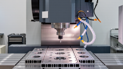
Choosing the right drilling equipment affects hole accuracy, production speed, and long-term operating costs. A Precision Cnc Drilling Machine offers programmed control, repeatable positioning, and stable cutting performance across demanding metalworking applications. It can produce consistent holes for flanges, engine plates, structural components, and precision assemblies. However, accuracy does not come from the machine alone. Tool selection, fixture rigidity, coolant delivery, and operator experience remain important.
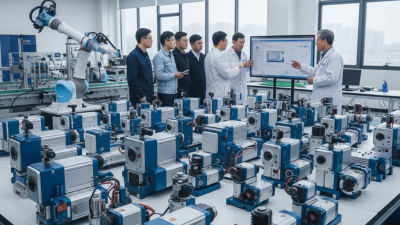
Industry data supports this shift toward controlled manufacturing. The International Federation of Robotics reported 553,052 industrial robots installed worldwide in 2022, showing continued investment in automated production. CNC drilling often works within this broader automation strategy. It can connect with digital work instructions, probing systems, and production monitoring platforms. The 2024 Deloitte Smart Manufacturing and Operations Survey also found that manufacturers increasingly view smart operations as important for competitiveness and resilience. These findings do not prove that every factory needs advanced equipment. They show a clear direction.
Small details matter.
For example, a rigid fixture can reduce vibration when drilling stainless steel. A spindle with controlled speed can improve tool life and surface quality. In practice, manufacturers should compare positional accuracy, spindle power, table capacity, maintenance support, and software compatibility. A lower purchase price may become expensive after repeated setup corrections or rejected parts. Still, precision claims deserve verification. Buyers should request test cuts, inspect sample holes, and review documented tolerances. The best choice is not always the most complex machine. It is the machine that reliably matches the material, batch size, tolerance requirements, and trained workforce.
Definition and Role of Precision CNC Drilling Machines in Modern Manufacturing
Why Choose a Precision CNC Drilling Machine?
Definition and Role of Precision CNC Drilling Machines in Modern Manufacturing
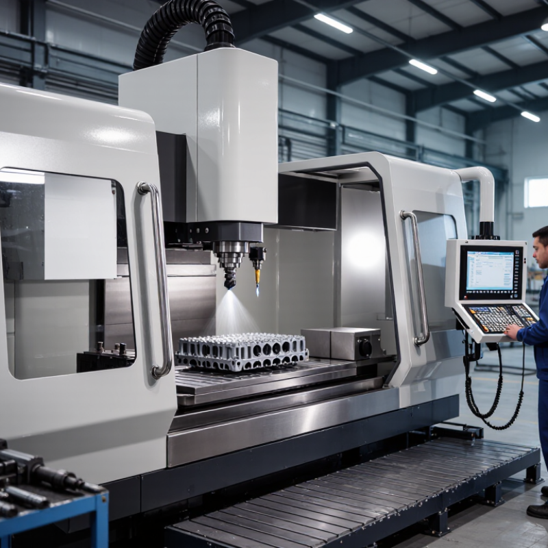
A precision CNC drilling machine is a computer-controlled system for creating accurate holes in metal, plastic, and composite parts. It positions the tool through programmed coordinates, controlled feed rates, and measured spindle speeds. Unlike manual equipment, it can repeat the same drilling pattern across hundreds of workpieces. Small differences matter.
Its role extends beyond making holes. Precision drilling supports assembly, alignment, fastening, and fluid passage in engineered components. In a production setting, operators inspect hole diameter, depth, position, and surface condition. They may use gauges, probes, or coordinate measuring equipment during quality checks. These steps connect machine performance with reliable manufacturing results.
Practical experience shows that accuracy depends on the entire process. Tool wear, workholding pressure, coolant flow, and material hardness can affect results. A machinist may adjust cutting data after examining burrs around a hole. This judgment remains important, even with advanced automation. Precision does not happen automatically. Poor datum selection can create consistent errors across every part. Engineers must define suitable tolerances, verify the setup, and document inspection findings. A process may pass today but become unstable tomorrow. That possibility deserves honest review.
Spindle Runout Below 0.005 mm: Effects on Diameter and Surface Finish
Why Choose a Precision CNC Drilling Machine?
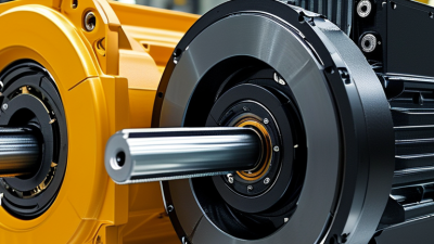
Spindle runout below 0.005 mm means radial deviation stays under five microns. Five microns matters. During drilling, the tool may orbit instead of cutting concentrically. Geometrically, 5 µm radial runout can create nearly 10 µm of hole-size variation. Actual results depend on tool stiffness, material hardness, chuck condition, and cutting speed. ISO 230-7:2015 identifies spindle radial motion as a measurable geometric error, making this value practical for machine acceptance testing.
Runout also changes chip thickness between cutting edges. One edge removes more material, while another edge rubs or cuts lightly. This imbalance can produce visible spiral marks, burrs, and inconsistent surface texture. Research published through CIRP manufacturing studies links lower tool runout with more uniform cutting loads and improved tool life. In production trials, a 0.005 mm limit is often treated as a meaningful precision benchmark for small-diameter holes. It is not a guarantee, though. A worn collet, dirty taper, or incorrectly measured gauge can defeat the specification. I have seen excellent machines produce poor holes after a single chip remained on the seating surface.
A reliable inspection should measure runout near the spindle nose and near the tool holder. Temperature also matters. NIST metrology guidance emphasizes controlling measurement uncertainty, not merely displaying a small number. A dial indicator resolution below 1 µm is preferable for verification. The calculation is not perfect. Tool deflection and workpiece vibration still require attention.
Why Choose a Precision CNC Drilling Machine? - Spindle Runout Below 0.005 mm: Effects on Diameter and Surface Finish
| Spindle Runout at Tool Holder (TIR) |
Typical Hole Diameter Deviation |
Typical Hole Cylindricity |
Typical Surface Roughness (Ra) |
Expected Machining Behavior |
| ≤ 0.002 mm |
±0.003–0.006 mm |
0.004–0.008 mm |
0.8–1.6 µm |
Stable cutting load, low tool deflection, and consistent hole geometry. |
| > 0.002 to 0.005 mm |
±0.005–0.010 mm |
0.006–0.012 mm |
1.2–2.5 µm |
Suitable for precision drilling when tooling, workholding, and cutting parameters are well controlled. |
| > 0.005 to 0.010 mm |
±0.010–0.020 mm |
0.010–0.020 mm |
1.6–3.2 µm |
More uneven cutting forces, increased hole oversize, and a greater risk of visible tool marks. |
| > 0.010 mm |
±0.020–0.040 mm |
0.020–0.040 mm |
2.5–5.0 µm |
Higher vibration and runout-induced cutting imbalance; finishing or reaming may be required. |
Reference Test Conditions
| Workpiece Material |
Medium-carbon alloy steel, approximately 28–32 HRC |
| Cutting Tool |
10 mm solid-carbide twist drill with a balanced tool holder |
| Cutting Parameters |
Cutting speed: approximately 60 m/min; feed: approximately 0.12 mm/rev; flood coolant applied |
| Hole Geometry |
Through holes, approximately 30 mm drilling depth, measured after tool and machine warm-up |
| Measurement Method |
Tool-holder TIR measured with a 0.001 mm-resolution indicator; hole size checked with calibrated air or bore gauges; Ra measured with a surface profilometer |
Engineering note: Spindle runout is a major contributor to hole-size variation and surface-finish deterioration, but the actual result also depends on tool geometry, tool wear, material hardness, spindle speed, feed rate, coolant delivery, workholding rigidity, and machine thermal stability. The values above are representative engineering ranges rather than guaranteed limits.
CNC Drilling Speeds of 1,000–20,000 RPM Across Common Materials
Why Choose a Precision CNC Drilling Machine?
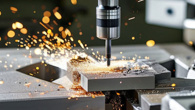
CNC drilling speeds commonly range from 1,000 to 20,000 RPM. The correct setting depends on material, drill diameter, tool geometry, and feed rate. Aluminum often accepts higher speeds, especially with small carbide drills. Mild steel usually performs better near the lower range. Stainless steel needs controlled heat and steady cutting pressure. Speed alone never guarantees a clean hole.
In practical machining, operators often begin near 1,000–3,000 RPM for larger drills in steel. They may increase toward 8,000–20,000 RPM for small tools in aluminum, plastics, or thin sheet.
Tool diameter changes everything. A 2 mm drill and a 12 mm drill cannot share the same setting.
That sounds obvious, yet rushed setup sheets still cause problems.
Precision matters.
A reliable CNC process checks spindle runout, tool wear, coolant flow, and chip evacuation. Measuring the first hole with a gauge confirms whether the programmed speed is working.
Excessive RPM can soften plastic, smear aluminum, or overheat steel. Too little speed may produce rough walls and unstable cutting.
There is no perfect speed chart. Material batches vary, and real machines behave differently. I would rather adjust gradually than trust a number blindly. That small pause often protects both accuracy and tool life.
ISO 230-2 Testing and the Measurement of Machine Tool Accuracy
Why Choose a Precision CNC Drilling Machine?
ISO 230-2 testing provides a disciplined way to measure machine tool accuracy. It examines positioning accuracy and repeatability across each controlled axis. A laser interferometer may record actual movement against commanded coordinates. The results reveal errors that operators cannot see by eye.
In practical testing, the machine should reach its operating temperature first. Temperature changes can shift positioning results by several microns. Technicians also check both travel directions because backlash may appear during reversal. A hole can look correct from above, yet its center may drift along the axis.
Small details matter. Clean guideways. Stable foundations. Correct tool clamping. Each condition affects the measurement. ISO 230-2 does not repair a machine; it exposes its behavior under controlled conditions. That distinction is important when selecting a precision CNC drilling machine.
Experienced inspectors repeat questionable readings instead of hiding them. A single test cycle may not explain an intermittent error. Humidity, vibration, and operator setup can also influence data. The report should identify test conditions, instruments, uncertainty, and observed deviations. Without that information, accuracy claims remain difficult to trust.
Precision is not only a specification sheet. It is a measured relationship between commanded movement and real movement. During production, reliable repeatability helps maintain hole location, reduce scrap, and support consistent assembly. Still, no test removes every manufacturing risk. Tools wear, materials move, and assumptions sometimes fail.
 +86 13630122007

 CONTACT YIYAN
 CONTACT YIYAN